
How to Create the Best Low Cost Multipath RF Fading Simulations

USB and Ethernet programmable solid-state RF digital attenuators,switches, and power dividers / combiners are a critical part of mobile network test platforms when flexibility in controlling wireless signalsis vital. Multipath fading is a commonly occurring problem with obstacles, such as mountains or buildings, absorbing and reflecting signals. Small, programmable test devices offer flexible features that can be used in fading simulation applications where multipath scenarios often occur. Applications include handover testing, radar processing, digital radio communications, and GPS receivers. In these cases, the fading simulator and customized test system offering multipath switching is the key to optimizing commercial and military mobile network performance.
What is a Wireless Handover?
A handover, or handoff, occurs when an outgoing cellular call is transferred from one cell to an adjacent cell as a cell phone or mobile device is moving through a network coverage area. Cells are physical areas that have cellular coverage. Handover is used with cellular networks, such as LTE or Wi-Fi networks. Some cellular services, including Google’s Project Fi, can even enable handovers between Wi-Fi and LTE with intelligent handover techniques.
What's critically important to understand is that the best cellular networks must rely on multiple frequency channels because any signal sent out by a base station can be attenuated by obstacles in the environment at any time. This challenge is ever-present to those involved in 5G. Soft handovers were developed as a solution to calls becoming unreliable due to fading. This is where a connection to the current cell is only broken after a steady connection to the target cell is established. This is known as ‘make-before-break’. Hard handover occurs when the mobile connection from the source is broken and the connection to the target is made afterwards. This is known as ‘break-before-make’. Hard handovers allow for a more efficient use of channels as only one channel is necessary to enable a hard handover. An additional benefit is this simplifies the design of next-generation 5G mobile phones. Why? Because it does not necessitate the need for parallel processing of several channels. So, while soft handovers may require more channels, and a mobile phone can receive two or more channels in parallel, the chances of a signal in all the channels being interrupted is much lower and dropped calls are highly unlikely in soft handover networks.
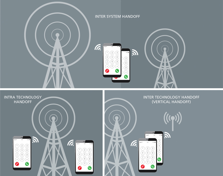
Handover can occur between “sectors” of the same site, known as intra system handover. Sectors are different areas of coverage from the same base station, and multiple ‘sectors’ can occupy one ‘cell’. Inter system handover can often occur with a fast-moving target, where the target connection is established from one cell to a completely different cell or base station. More recently, cellular technological advances have enabled vertical handover, such that a mobile phone connects between cellular networks and wireless LAN (WLAN) for greater accessibility. While cellular networks can offer lower data rates over large areas, WLAN technologies can potentially compensate for this as it offers higher data rates over smaller areas.
Multi-path Fading and Handover Applied
Firstly, network engineers generate a ‘neighbor list’ of potential target cells for handover from selected source cells. Then, as a call is ongoing, the source channel’s signal transmission strength is monitored to assess when a handover request by the mobile phone of base station is necessary. In this complex process, the base stations in the ‘neighbor list’ and the mobile phone are connected and monitoring each other for the best target cell to connect to.
Network engineers have designed several monitoring methods to ensure wireless handover takes place seamlessly. The parameters that are tracked are dependent on the types of network modes that the mobile phone receiver and base station antenna is communicating with. Some of these modes include GSM, UMTS, LTE, and CDMA. Ultimately, the received signal level and received signal quality is tracked in the network measurement reports (NMR). Although, this is more complex with vertical handover where metrics should include user preference, network conditions, application types, cost, etc. In GSM networks, the Rxlevel indicates the power level of the received signal and is measured in decibels (dBm) and RxQual is an integer value representing the quality of voice at the receiver. The integer value of RxQual corresponds to the number of bit errors in a number of bursts. For UMTS, the received signal code power (RSCP) is another measurement of received signal power over a communication channel, and is measured in dBm. The Ec/Io is the ratio of the received energy per chip and the interference level measured in dB. In LTE handover measurements, the reference signal received power (RSRP) is used to estimate path loss, while reference signal received quality (RSRQ) indicates the quality of the received reference signal. In essence, RSRQ is a ratio between RSRP and the reference signal strength indicator (RSSI).
So, is time to resolve your complex multipath fading simulations?
Check out our latest updates at: https://vaunix.com/updates/
And to to learn even more about Handover Testing, download our tech brief:
“Creating Advanced Handover Test Systems with Low-cost Programmable Devices”.
Vaunix | 978-662-7839 | 7 New Pasture Road | Newburyport, MA 01950


Vaunix | 978-662-7839 | 7 New Pasture Road | Newburyport, MA 01950