
What to Understand Before Choosing Your RF Signal Generator: Part 1
By Scott Blanchard
What is a RF Signal Generator?
An RF Signal Generator is an electronic piece of test equipment that generates RF signals over a wide variety of frequencies with high spectral purity, stable frequency, and stable amplitude. RF signal generators are not to be confused with vector signal generators, which generate RF signals but also have complex digital modulation capabilities with formats such as QPSK, QAM, FSK, BPSK and OFDM. RF signal generators offer modulations that include amplitude modulation (AM), frequency modulation (FM), phase modulation (φM) and pulse modulation.
Specifications
The test equipment market offers a myriad of RF signal generators with additive features for a vast range of applications. Many datasheets in the industry come with a slew of specifications that can be confusing. RF signal generator specifications fundamentally break down to an assessment of the quality of the output signal, this includes the range, resolution, and accuracy of the frequency and power outputted, as well as switching time, and spectral purity.
The frequency range and output power are important basic specifications of a signal generator to ensure that the equipment operates in a range of frequencies and power that supports a test. The frequency range is often the strongest determining factor for the price range of a signal generator, the higher the frequency, or wider the frequency band, the more expensive the product becomes. Power output is normally specified in decibels referenced to 1 milliwatt (dBm) but is often necessary to convert into watts (W). The typical maximum output power is +13 dBm, 20 mW, while the minimum output power can go below -100 dBm depending on the amount of internal attenuation.
Aside from frequency range and output power, these are a few of the other important specifications you should be aware of for your signal generators:
- The resolution is the smallest frequency or power/amplitude increment in Hz or dBm.
- Switching speed is a measurement of the speed at which the source alternates from one amplitude to another.
- The measurement of frequency accuracy is listed in parts-per-million (ppm) and is a measurement of the frequency drift over a year. This measurement is typically obtained from the generator’s internal clock as well as statistical analysis from the aging of the signal generator.
- Power accuracy, also known as amplitude accuracy, denotes the accuracy of the power outputted by the instrument over full power range and is measured in dB.
Oftentimes, measurements are power and frequency sensitive, so taking note of the power accuracy and frequency accuracy is essential to more definitively assessing a device under test (DUT). For instance, to best compare the 3 dB cutoff frequency of two different filters it would be important to be able to accurately assess the exact frequency point at the cutoff in order to draw an accurate comparison. This would require tighter specifications for frequency resolution and accuracy.
There are several measurements to assess the spectral purity of a signal generator including phase noise, spurious, harmonics, and subharmonics. Phase noise is essentially a measurement of the “jitter” of a signal. A lack of frequency stability in the time domain can translate to noise in the frequency domain. Phase noise measures the level of noise in a 1 Hz bandwidth relative to the level of the carrier signal and is often measured in dBc/Hz. Limiting the phase noise of a signal source allows for a more reliable signal generator overall. Harmonics are the integer multiples of the continuous wave (CW) signal source (i.e. 1, 2). Subharmonics are signal impurities that occur at non-integer multiples of a generated signal’s carrier frequency (i.e. 0.5, 1.5). The signal source contains many nonlinear elements that will come out as harmonics in the frequency spectrum. The non-harmonic spurs, or spurious signals, come from non-linearities in the components of a signal generator that are not the signal source, such as the power supply.
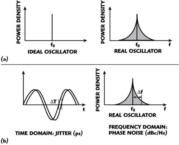
Fig 1: Frequency spectrum of ideal and real oscillators the jitter in time domain relating to phase noise in the frequency domain. (Source: http://synergymwave.com/articles/2007/09/)
Additive Specifications
There are number signal generators that come with additive ingredients such as vector modulation, pulse shaping filters, multiple bus interfaces, controlled injection of additive white gaussian noise (AWGN), etc. Typically, the more additive benefits, the higher the cost, the bigger the equipment, and less ease of use. While many customers find these additions necessary to their particular application, there are many engineers and technicians that want a basic and affordable signal generator without all of the “bells and whistles.”
To learn more about our latest signal generators, download the datasheets of the LMS-802DX and LMS-183DX here or contact us with any questions.
Vaunix | 978-662-7839 | 7 New Pasture Road | Newburyport, MA 01950


Vaunix | 978-662-7839 | 7 New Pasture Road | Newburyport, MA 01950